 : Do not work on or under a vehicle supported only by a jack. Always
support the vehicle on safety stands.
|
Raise and support the vehicle.
| : | Apr 16, 2007 |
| In this procedure, the body is removed from the integrated body-frame. This procedure can only be performed using a 2-Post ramp. |
| . |
Raise and support the vehicle. |
| . | Remove the wheels and tires. |
| . | Disconnect the battery ground cable. |
| . | Drain the coolant. |
| . | Recover the A/C refrigerant. |
| . | Remove the air cleaner assembly. |
| . | Remove the TCM. |
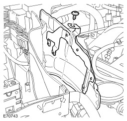
| . | Remove the engine compartment RH upper heat
shield.
 |
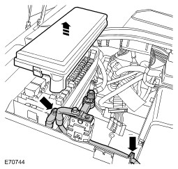
| . | Release the battery positive cable.
 |
| . | Remove the battery compartment side wall.
|
| . | Remove the battery compartment side wall
extension. 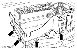 |
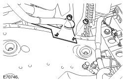
| . | Release the battery positive cable bracket.
 |
| . | Release and disconnect the 2 engine harness
electrical connectors. 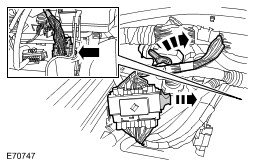 |
| . | Release and disconnect the 2 transmission
harness electrical connectors. 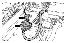 |
| . | Release the engine and transmission harness
cassettes, position the harnesses aside.
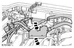 |
| . | Remove both front fender splash shields. |
| . | Remove the fender lower moulding.
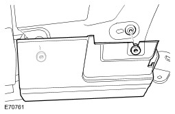 |
| . | Remove the front bumper cover. |
| . | Remove the radiator lower air deflector.
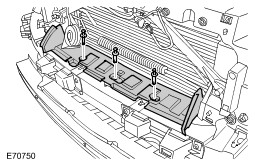 |
| . | Remove the ride and handling optimization switch
assembly. |
| . | Release the power steering fluid reservoir from the retaining bracket. |
| . | Remove the windshield washer reservoir filler neck. |
| . | Disconnect the 2 hoses from the coolant
expansion tank.
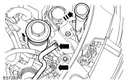 |
| . | Remove the coolant expansion tank.
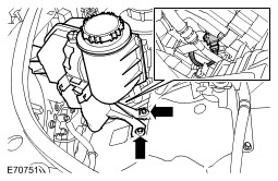 |
| . |
Disconnect the brake booster vacuum hose.
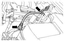 |
| . |
Disconnect the A/C compressor low pressure line.
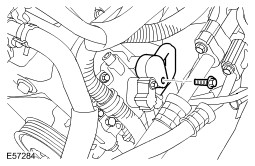 |
| . |
Disconnect the A/C condenser high pressure line.
|
| . | Remove the radiator securing pegs.
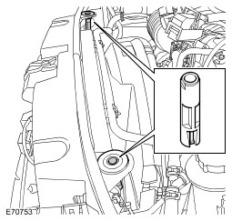 |
| . | Release the 2 heater coolant hoses.
|
| . | Disconnect the 2 heater coolant hoses.
.jpg) |
| . | Disconnect the washer reservoir 3 electrical connectors. |
| . |
:
Disconnect the 2 washer pump hoses. .jpg) |
| . | Disconnect the ambient air temperature sensor
harness.
.jpg) |
| . | RH side front: Release the air suspension line from the wiring harness clip. |
| . | RH side front: Release the ABS sensor lead.
|
| . | RH side front: Disconnect the engine ground
cable from the body.
.jpg) |
| . | RH side front: Disconnect the 2 body harness
electrical connectors.
|
| . | RH side front: Release the body-frame harness.
.jpg) |
| . |
RH side front: Release the brake line.
.jpg) |
| . | LH side front: Release the ABS sensor lead.
|
| . | LH side front: Disconnect the brake pad wear
sensor electrical connector.
.jpg) |
| . | LH side front: Release the 2 air lines.
.jpg) |
| . | LH side front: Remove the engine compartment
heat shield.
.jpg) |
| . | Disconnect the steering column lower shaft from
the steering column.
.jpg) |
| . | LH side front: Disconnect the 3 body harness
electrical connectors. .jpg) |
| . | LH side front: Release the integrated body frame
ground cable.
.jpg) |
| . |
LH side front: Release the brake line.
.jpg) |
| . | Remove the rear fender mouldings. |
| . | Remove the RH rear fender splash shield.
.jpg) |
| . | Remove the rear bumper cover. |
| . | Remove the fuel filler flap assembly. |
| . | Release the fuel filler neck.
.jpg) |
| . |
RH side rear: Disconnect the brake line.
.jpg) |
| . | LH side rear: Disconnect the 2 body harness
electrical connectors. .jpg) |
| . |
LH side rear: Disconnect the brake line.
.jpg) |
| . |
LH side rear: Disconnect the suspension air compressor intake line.
.jpg) |
| . |
Release the parking brake emergency release cable. .jpg) |
| . | Remove the transmission undershield.
.jpg) |
| . | Remove the transmission heat shield.
.jpg) |
| . | Release the selector cable.
.jpg) |
| . | Remove the body mount retaining bolts.
.jpg) |
| . | Temporarily install the road wheels and tires.
|
| . |
:
:
Raise and support the body.
.jpg) |
| . |
:
:
Install the body mounts.
|
| . |
Install the body to the integrated body frame.
|
| . | Remove the wheels and tires.
|
| . | Tighten the integrated body-frame to body bolts to 133 Nm (98 lb.ft). |
| . | Attach the selector cable. |
| . | Secure the parking brake emergency release
cable.
|
| . | LH side rear: Connect the suspension air
compressor intake line.
|
| . | LH side rear: Connect the brake line.
|
| . | LH side rear: Connect the 2 body harness electrical connectors. |
| . | RH side rear: Connect the brake line.
|
| . | Secure the fuel filler neck.
|
| . | Install the fuel filler flap latch assembly.
|
| . | Install the rear bumper cover. |
| . | Install both rear fender splash shields. |
| . | Install both rear fender mouldings. |
| . | LH side front: Connect the brake line.
|
| . | LH side front: Connect the integrated body frame
ground cable.
|
| . | LH side front: Connect the 3 body harness electrical connectors. |
| . |
:
Connect the steering column lower shaft.
|
| . | LH side front: Install the engine compartment
heat shield.
|
| . | LH side front: Secure the air lines to the clips. |
| . | LH side front: Connect the brake pad wear sensor
electrical connector.
|
| . | LH side front: Connect the ABS sensor lead.
|
| . | RH side front: Connect the 2 body harness electrical connectors. |
| . | RH side front: Secure the body-frame harness.
|
| . | RH side front: Connect the brake line.
|
| . | RH side front: Connect the engine ground strap
to the body.
|
| . | RH side front: Connect the ABS sensor lead.
|
| . | RH side front: Install the air suspension line to the wiring harness clip. |
| . | Connect the ambient air temperature sensor
harness.
|
| . |
:
Connect the washer pump hoses. |
| . | Connect the washer reservoir electrical connectors. |
| . |
Connect the A/C compressor low pressure line.
|
| . |
Connect the A/C condenser high pressure line.
|
| . | Connect the brake booster vacuum hose to the
intake manifold.
|
| . | Install the coolant expansion tank.
|
| . | Connect the coolant hoses to the expansion tank.
|
| . | Install the windshield washer reservoir filler neck. |
| . | Install the power steering fluid reservoir.
|
| . | Install the radiator securing pegs. |
| . | Install the radiator lower air deflector.
|
| . | Install the front bumper cover. |
| . | Install both front fender splash shields. |
| . | Install the fender lower moulding.
|
| . | Align the engine, transmission harness and cassettes. |
| . | Connect the 2 engine harness electrical connectors. |
| . | Connect the 2 transmission harness electrical connectors. |
| . | Install the engine and transmission harness cassettes. |
| . | Install the TCM. |
| . | Install the battery compartment side wall extension. |
| . | Install the battery compartment side wall.
|
| . | Install the engine compartment upper RH heat
shield.
|
| . | Install the battery positive cable.
|
| . | Connect the heater coolant hoses.
|
| . | Secure the heater coolant hoses
|
| . | Install the air cleaner assembly. |
| . | Connect the battery ground cable. |
| . | Refill and bleed the cooling system. |
| . | Recharge the A/C system. |
| . | Bleed the brake system. |
| . | Install the wheels and tires. |
| . | Install the ride and handling optimization
switch assembly. |
| . | Adjust the selector cable. |
| . | Install the transmission heat shield.
|
| . | Install the transmission undershield.
|