Disclaimer: the features described below are taken from my own Z3801A. They are intended for academic purposes only and may not be used for businesses of any kind. The descriptions below are believed to be correct. However, I cannot be held responsible for any damage or personal injury that results from using these descriptions. In other words, you are welcome to ask questions, suggest alterations and use this information at your own risc - but basically you are on your own if problems of any kind arise ;-)
The outer oven of the Z3801A GPS disciplined crystal oscillator is used to keep the ambient of the inner oven of the oscillator (HP10811) at a roughly constant temperature of somewhere between +60...+65 °C. The exact value is not known to me. Because the Z3801A is specified from 0...+50 °C, and the HP10811 is specified for ambient temperatures of not more than +71 °C, I think this makes sense.
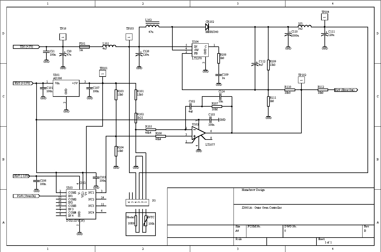
The oven control circuit is located on the power supply PCB. Including its DC-DC converter the circuit occupies about 1/3 of the board space. It consists of the following parts:
In addition there is one output to the main controller board. This allows the main CPU to measure the percentage of heating power in the ON state.
During normal operation the NTC resistor samples the temperature of the oven. Its resistance is approximately 16.21k, i.e. U102 is in the linear region. Should the temperature of the NTC decrease, its resistance increases and pin 6 of U102 goes to a lower voltage. Conversely, increasing temperature results in a higher output voltage at pin 6. According to the data sheet the maximum output swing is from ~0 ... 13.5V.
U104 works in normal boost mode. The voltage at the feedback input pin 2 is compared to an internal reference voltage of 1.244V, and the output steered to keep the difference between pin 2 and reference at zero. At the lowest possible output voltage of U102 R110 lies in parallel to R111, and the output voltage of the switching regulator goes up to 19.4437V. The minimal output voltage is 5V (minus one diode drop) which is reached for a control voltage of 10.86V at U102/pin 6. For higher control voltages U104 shuts down.
Because the heater resistor is not tied to ground but to +5V, minimum heater voltage is exactly 0V. Therefore the heater power can be adjusted from 0 ... ~11 W.
C115 and R107 define the dynamic behaviour. This structure is a classical proportional-integral servo, see simulations below. In addition, C112 makes for a soft start without any overshoot neither in input current nor output voltage. The associated time constant is much faster than the loop, however. Loop performance is not affected in a notable way!
Last but not least, the output voltage of U102 / pin 6 is available at P2/9. On the main CPU board there is another 10k series resistor, then 5.11k to ground and 2.15k to +5V. The resulting input voltage on pin 3 of the 8-bit AD-converter U35 / ADC0838 is therefore in the range +3.27 ... +4.22V (equivalent to 0 ... 13.5V on U102 / pin 6).
If the oven is below the normal temperature U102 saturates near 0V and the heater receives full power. The oven mass slowly gets hotter, until the servo loop reaches its linear range and locks.
The main CPU controls the oven through P2/8. If the voltage at U103/pin 1 is below ~2.4V the non-inverting input of U102 is pulled towards +15V, and the output pin 6 saturates instantly near 13.5V. In turn, U104 shuts down and heater power is zero. On the main CPU board the control pin has a pull-down resistor to ground (10k), and a 1k series resistor to pin 10 / PGP5 of the main CPU U33 / MC68331.
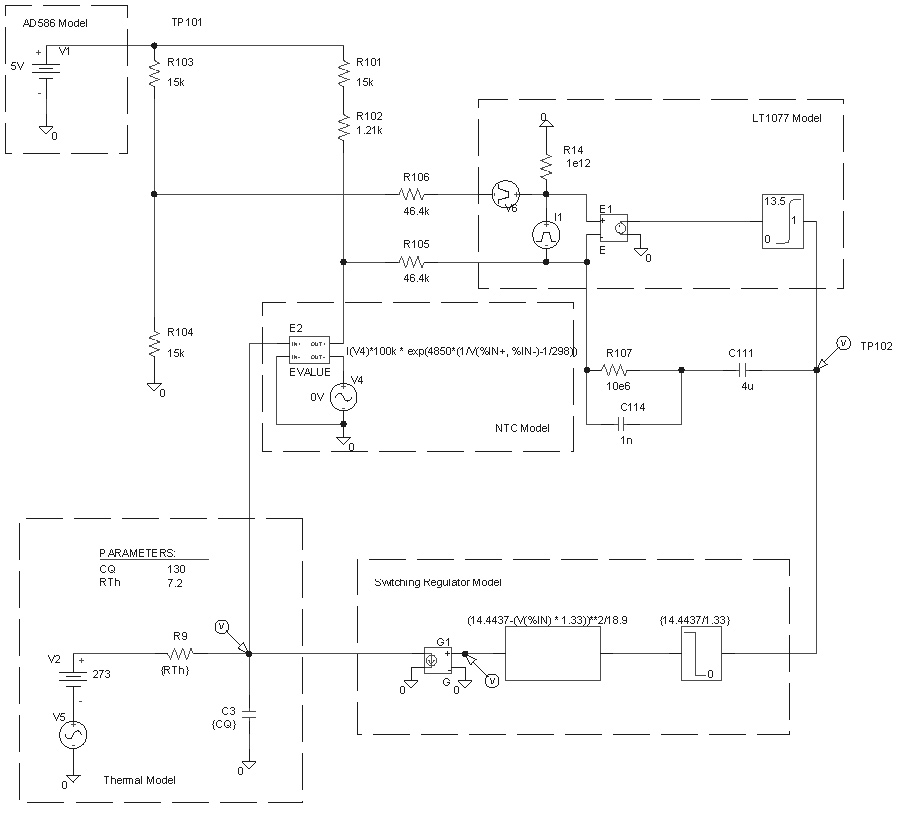
With a demo version of PSPICE the servo loop was simulated. The different sub-parts are modeled by simple substitutions for the op-amp, the switching regulator, the NTC and the thermal model of the oven.
For the NTC the formula Rt = Rn * exp(Beta(1/T - 1/Tn) is used. The normalizing Temperature Tn = 25°C, with an associated resistance Rn = 100k. Choosing Beta = 4850 results in Rt = 16.21k @ ~62.5°C.
The electrical equivalent to the thermal oven model consists of a capacitor representing the heat capacity, a voltage source representing ambient temperature and a resistor for the heat conduction between oven mass and ambient. In this equivalent model voltage, current, resistance and capacity in the electrical 'world' represent absolute temperature, power, thermal resistance and heat capacity times mass in the thermal world, respectively. E.g in the box 'thermal model' below, input to the thermal model is power, output is temperature, and ambient temperature is a variable parameter.
How are the thermal model parameters determined? For the capacitor this was easy: put the oven mass on a scale (~0.145kg) and multiply by the specific heat capacity of aluminium (896 J / kg K). For the thermal resistance one could take surface area (~0.032m^2) and find heat conduction values of typical foams. The problem is to find the right foam and correctly guess the losses due to slots in the foam, and cabling. However, it is much easier to measure the voltage on TP102 and adjust the thermal resistor in the model to obtain the same value. This resulted in a resistor of Rth = 7.2R.
With this model one can easily find answers to several question: what is the impact of offset bias (< 0.002K), offset voltage (< 0.02K) or resistor tolerance (< 1.4K).
Perhaps the most interesting question: what is the impact of temperature changes of the ambient. To find an answer two scenarios where simulated: 1. fast switching from 0°C to +50°C and vice versa, 2. fast switching from -10°C to +60°C and vice versa. Although one could barely do this test in practice (without special two-temperature-testers, that is) it gives insight in the loop behaviour.
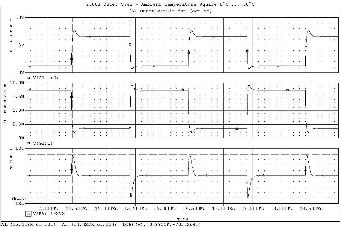
The upper trace shows the voltage at TP102, the middle trace is heater power in Watts and the lower trace shows the oven mass temperature in °C. The traces show nice, smooth curves, and after about 200s the loop has stabilized after a step in ambient temperature.
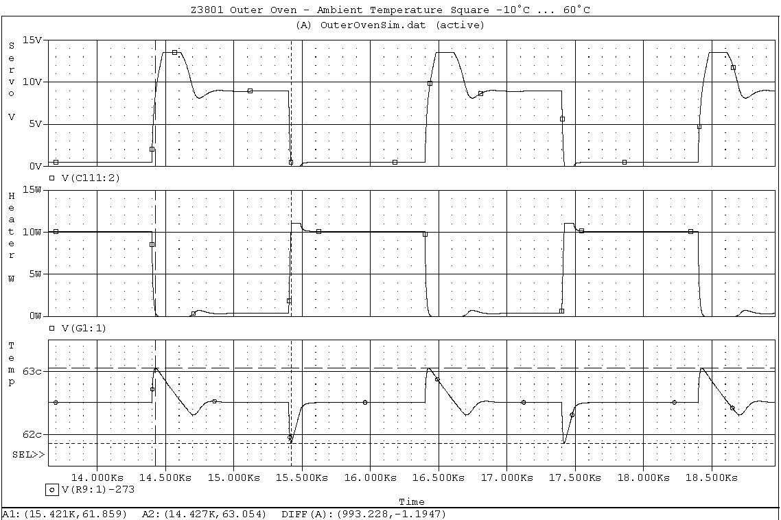
The same traces as above. Obviously the servo loop saturates on both high to low and low to high steps. On -10°C to +60°C step it takes roughly 500s to stabilize, and during almost 250s the loop is unlocked!
last updated: 24 January 2004 mailto: stefan(dot)hegnauer(at)gmx(dot)ch